by Ulrich Simon, design at Alexander Schleicher Segelflugzeugbau
While most people consider a sailplane to be more dangerous than a motor-powered aircraft, gliding aficionados say it is safer because there is no engine that can fail and cause a disaster. A skilled glider pilot can currently ride the thermals — the updrafts of warm air that keep the aircraft aloft — for up to 1,000 km over a 10-hour flight.
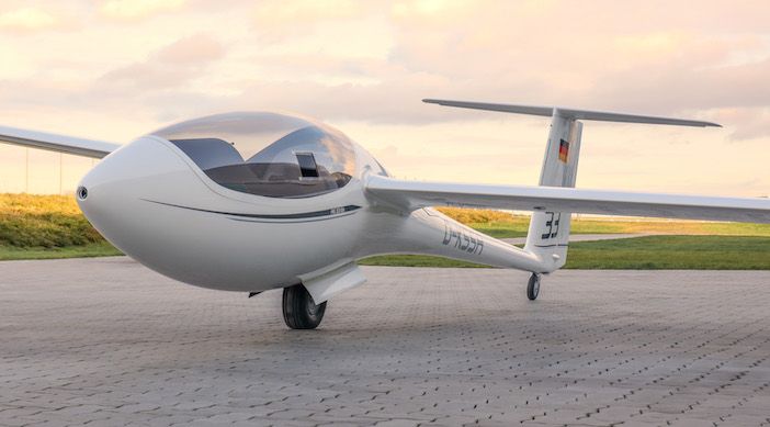
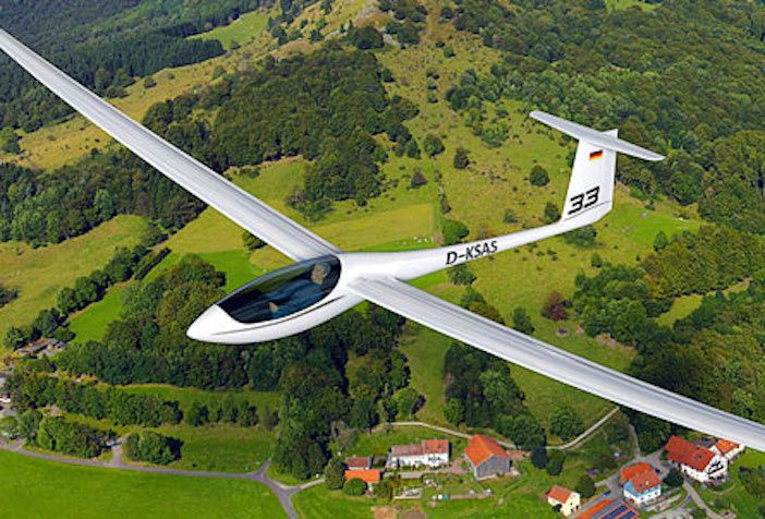
But increasing the speed and range requires reducing the overall drag on the glider. Engineers at Alexander Schleicher Segelflugzeugbau (AS Sailplanes) have used structural and composites simulation software to design a wing with a new composite structure and with a smaller surface area to reduce the drag of the AS 33 aircraft.
Aerodynamic, structure and materials challenges
Best-in-class gliders used in competitions weigh from 400kg to 600kg. They have an 18m wingspan and a 10.5 square meter wing surface area, with a wing thickness of only 10cm.
While the wingspan and thickness are very close to practical limits, AS Sailplane engineers believed the surface area could be reduced from 10.5 square meters to 10 square meters to cut the aerodynamic drag significantly. By keeping the 18m wingspan constant, they produced a wing with a smaller average chord and therefore a reduced wing thickness.
While that may not sound like a big design change, it is massive in an aircraft that has been around for a long time and is already very close to its optimal design. The change required the team to overcome a host of challenges.
Reducing the wing surface area produces less lift, so the aerodynamics of the system must be improved to compensate. A smaller wing also has less space for structural elements, so engineers needed to improve the design so that the wing can carry the same loads while maintaining strength. Engineers also wanted to investigate if connecting the wing high up on the fuselage was better than a mid-fuselage join in terms of strength and drag.
An additional challenge was to optimize the winglets — the small, upturned tips of the wings — which reduce vortex airflow at the ends of the wing, further reducing drag. Because most of the sailplane is made of composite materials, except for the metal landing gear and mechanical control system, engineers explored an all–carbon-fibre design instead of the commonly used combination of glass fibres and carbon fibres embedded in a polymer matrix.
Answers for aerodynamics
AS Sailplane engineers started the project with an in-house analytical tool that the company had been using for several years, but they soon realized that it would be insufficient for the task. Contracting the work out to universities proved to be too expensive, inflexible and not conducive to building in-house expertise.
The company opted to use ANSYS simulation software for finite element analysis and the computational fluid dynamics aspects, which could be analyzed in Fluent. Structural aspects of the design could be looked at in Mechanical and composite solutions in Ansys’s Composite PrepPost software, meaning only one software supplier was required.
First, the engineers applied ANSYS Fluent to solve a question that had been puzzling sailplane engineers for several years – what is the best place to connect the wing to the fuselage for the least drag? Some had argued that attaching the wing at a high position on the fuselage prevents detachment of the boundary layer airflow from the aircraft body, leading to less drag; others contended that attaching the wing to the middle of the fuselage requires a smaller connection cross section, thus reducing drag, while simultaneously increasing the undesirable boundary flow detachment phenomenon. The discussion had persisted for years because there was no way to answer the question definitively using wind tunnel testing. Standard calculations were also insufficient, so simulation was needed.
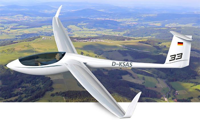
After analyzing six wing–fuselage connection positions using Fluent 3D CFD calculations, the engineers determined that the mid-wing configuration produced less drag, especially in high-speed cornering situations, so they settled on the mid-wing–fuselage connection point for the AS 33. The detachment of the boundary layer airflow proved to be a smaller factor than previously thought. Without CFD, they would not have been able to settle this long-standing argument. A similar simulation process was used to determine the optimal positioning of the winglets.
Structures and materials
The smaller wing of the new AS 33 sailplane had to support equivalent or even higher loads than its predecessors because the weight of the fuselage of the AS 33 was increased to accommodate an enhanced, crash-optimized cockpit and pilots now carry more electronic equipment with them. Supporting higher loads with smaller wings requires structural improvements. Engineers decided to use an all– carbon-fibre composite material instead of the carbon and glass fibre mix used previously. Carbon fibres are stronger than glass ones and can support higher loads.
AS Sailplane engineers realised that they needed finite element analysis and composite simulations available to prove that this new composite construction would be strong enough for the task at hand.
Because of the needle-like proportions of the fibres, the strength of the resulting composite has directional properties based on the fibre orientation and layered plies of the composite. This adds complexity to the design process. AS Sailplane engineers decided to solve this problem using ANSYS Composite PrepPost simulation with its “model as you build it” approach.
The simulation software was used to model the individual composite plies and get a close-up, detailed view of the resulting layup. The engineers explored five different composite models in the entire assembly, with the total number of plies ranging from 100 to 300. They then analysed the structural integrity using composite failure criteria and any problems with the structure.
With the combination of very high loads, a small wing and little space for support structure, it was necessary to calculate the stresses and strains in the materials accurately for each ply using Composite PrepPost. Engineers then iteratively modified their simulation models by adding more plies or changing already existing ply properties such as ply extent, fibre orientation or materials at high load points to eliminate any weak points in the design.
They also used the software to design the spar that runs the length of the wing on the interior and withstands the bending forces to which the wing is subjected. The spar is made of the same composite material as the wings and fuselage.
Engineers experimented virtually using the ply-wise modelling capabilities of Composite PrepPost to create a robust structure, using the solid modelling features to evaluate this difficult structural part. Using the simulation software they studied the 3D stress state along the wing and detect any potential problem areas.
Finally, engineers performed modal analyses to prevent vibrations that lead to wing fluttering in flight — a dangerous situation.
In the largest model used to simulate the vibration modes of the entire glider, engineers produced a mesh consisting of 1.5 million cells, which were mostly quadratic elements. The automated meshing process took about 15 minutes. Using two computer cores, the simulations lasted 20 minutes for a linear solution and 10 hours for a nonlinear solution. They typically performed 10 to 50 simulation runs to optimise the design, detect problems and calculate multiple load cases.
Validation
Ultimately, AS Sailplanes’ engineers tested the wing structure for the European Aviation Safety Agency to gain approval for its use. ANSYS simulations played a major role in demonstrating the structural integrity of the new design that led to the agency’s approval. It would not have been possible for AS engineers to reduce the sailplane’s wing surface area by 4.7% (to 10 square meters) and pass this test without the use of simulation software – the ability to perform numerical calculations to see the high stress areas of the model made this innovation in sailplane design possible.
The AS33 made its maiden test flight last month. For more information on the design and testing of the aircraft go here. More information on Ansys’ simulation solutions is here.
