Words by Jack Roper
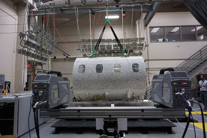
Digital image correlation is becoming a trusted instrument for measuring strain and deformation in aerospace testing. A test sample is painted with dots, cameras record how the dots move when loads are applied and software correlates these images to produce full-field strain or deformation data.
Digital image correlation (DIC) can measure the behavior of full-sized rocket-sections or microscopic fibers, as well as record split-second detonations or
quasi-static events lasting many hours. The technique, which uses high-speed cameras, has decisive advantages over traditional sensors and is evolving into a reliable, point-and-shoot industrial solution. “At NASA Langley Research Centre [LaRC] we characterize damage in structures and materials,” says LaRC contractor, Dave Dawicke. “We run DIC on everything from small material tests to full-scale components and use it to validate our finite element analysis.”
DIC was developed by Mike Sutton in the 1990s. “Mike built a system with one camera that worked on a 2D plane,” Dawicke says. “He created pattern-recognition software to calculate displacements between images.” Accurate fracture-test results convinced NASA to invest in Sutton’s work.
“He then added a second camera to create a stereo system. That captured movements in three dimensions, which was a real game-changer.” Today, tests can involve many pairs of cameras.
Large load tests
During 2011, a NASA Marshall DIC team captured a full-sized rocket cylinder buckling under 2,000,000 lbs of downward pressure for the first Shell Buckling Knockdown Factor (SBKF). Data from this and subsequent SBKF test inform NASA’s modern launch vehicle designs.
“Rocket-casings were designed conservatively based on theoretical buckling loads derived in the 1950s,” Dawicke explains. “By testing how actual cylinder imperfections affected buckling-load, NASA aimed to use lighter structures with the same safety level.”
For the test, eight camera-pairs provided 360° coverage of the 27ft-diameter cylinder: probably NASA’s largest DIC test-subject ever. VIC-3D Digital Image Correlation systems supplied by Correlated Solutions were used.
“It’s like squashing a beer can,” Dawicke says. “But they didn’t know where it was going to buckle, and when it buckles it goes quickly. High-speed 3D DIC systems captured that buckling event.”
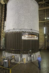
in 2011 (Image: NASA)
DIC vendors typically provide end-to-end solutions like Aramis, developed by German company GOM and delivered by US vendors like Trilion. “Aramis is both hardware and software,” says Trilion’s vice-president Tim Schmidt. “The primary hardware is usually a stereo pair of cameras on a bar. They have to be aligned and calibrated, so the system includes calibration objects, either plates or crosses.”
Earlier systems required expert alignment, but the trend currently is for the use of presets and automation to enable ease-of-use and accuracy. “Our 3D cameras are point-and-shoot instruments where users select a preset field-of-view and templates for analysis and reporting,” says Schmidt. “After the first test, you define twenty points of interest, then the results from subsequent tests happen automatically.”
Aramis has been used in blade-off testing, which is conducted to see if a fan blade breaking off within an engine will puncture the engine’s enclosure.
“Knocked-off blades could penetrate the cabin and decapitate a passenger, but a containment structure around the blades prevents that,” says Schmidt.
Engine manufacturers use DIC t0 test lighter materials for engine casings, like braided composites. “They explosively release one blade and we measure how the containment structure bulges and strains,” says Schmidt. “When blades come off, the whole engine goes violently out of balance. We also measure how the mounts securing it to the aeroplane respond to those beyond-normal forces.”
Sensor replacement
Crucially, DIC provides full-field data where traditional strain-gages yield only point-measurement. “It’s hard to position strain gages unless you know exactly where the largest strain will occur,” says Phillip L. Reu, the immediate past president of the International DIC Society (iDICs). “But with DIC, you just
spray-paint tens of thousands of detectors across an entire surface.”
Similarly, DIC can replace accelerometers in modal testing. “Gluing accelerometers all over a test object can influence vibration,” says Reu. “Full-field DIC measures acceleration everywhere at once and is a non-contact technique.”
However, Boeing lead engineer Alessandro Vieira sounds a more cautious note: “Complex geometries with lots of translation cause uncertainties,” he says. “These must be understood before industry has confidence in DIC for critical applications.” IDICs aims to provide information and certification around quantifying such uncertainties.
DIC can also do the work of LVDT (linear variable differential transformer) displacement sensors, wires which take time to attach and only measure in one direction. “Testing the new Space Launch System involves pushing and pulling huge hydraulic cylinders in different directions,” says Schmidt. “That’s much easier to capture with DIC.”
Dawicke agrees, “For full-scale tests the aircraft is a patchwork of sensors and wires and it’s hard to meaningfully pull that together. DIC provides a full-field picture with a coordinate system easily matched to FEA [finite element analysis] models. Strain-gages give better microstrain-level accuracy, but damage generally involves larger strains and displacements.”
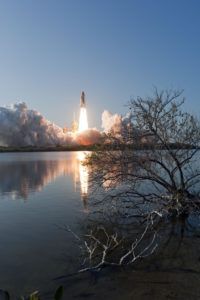
Validating FEA is a key DIC application. In 2003, Space Shuttle Columbia disintegrated on re-entry because a piece of foam punctured its wing during launch – a danger NASA’s models fatally underestimated. The subsequent return to flight program for the Space Shuttle required NASA to demonstrate the accuracy of its FEA against DIC data. “NASA converted the chicken gun used in bird-strike tests to fire a briefcase-sized piece of foam into an orbiter wing-section,” Schmidt says. “We took pictures at 27,000fps and the entire test lasted a fraction of a second.”
Dawicke has captured deformation at 2,000,000fps in explosive tests for NASA. By contrast, quasi-static tests unfold over many hours or even days. “Before the 2011 STS-133 Shuttle mission, NASA noticed loose foam on an external tank they were filling with liquid hydrogen and oxygen,” says Schmidt. “That’s exactly what caused the loss of Columbia, and removing the foam revealed several cracks on the tank.”
Schmidt’s team used DIC at the Kennedy Space Centre launchpad while the tank was filled over a 12-hour period. “We measured how it contracted and exactly where cracking occurred – due to bending aluminum reinforcement,” he says. Adding reinforcements fixed the problem and Aramis data validated NASA’s as-built section model to ensure modifications didn’t cause problems elsewhere.
Size matters
DIC can be performed at any speed and at any scale. “We’ve looked at 0.03in-diameter carbon-fiber bundles using a stereo microscope with two cameras coming in,” says Dawicke. “We calibrated them using a tiny grid and processed the images just as we do larger ones.”
Applying a good speckle-pattern is often said to be the hardest part of DIC and forms a popular discussion topic at iDICs conference. “Getting speckles becomes tricky at very small scales,” says Dawicke. “If you’re good with spray-paint, you can get a really fine mist. An airbrush can create even finer speckles – one company has developed a micro-stamper for electron microscope measurements.”
“We want to ensure we get quality results so that DIC continues growing as a trusted measurement,” says Reu. To this end, iDICs runs certification courses on how to avoid classic mistakes, such as with speckle patterns. ‘Too large a pattern on a specimen with high deformation in some areas makes your analysis region larger than necessary, which tends to smooth out deformation gradients,” Reu says.
Decalibration between two precisely-placed cameras is another potential pitfall: “If anything moves between the left and right lenses at a microscopic level, you no longer get accurate data,” says Schmidt. “For the STS-133 test, we calibrated our system on the ground, then they hoisted it 215ft to mount on the launchpad. Our aluminum bar had to be mechanically robust and NASA fabricated custom thermal insulation so it didn’t decalibrate because of temperature-changes.”
Violent high-speed tests bring different calibration challenges. “When the foam hits that wing, the whole room vibrates,” says Schmidt. “The camera-bar either has to be tough or insulated from those shocks.”
A hot topic
During descent, an ablative heat-shield will protect the 2020 rover now journeying to Mars. DIC has been used to show that this structure can survive the descent. “Because it was a flight-article, we couldn’t even touch it,” says Dawicke.
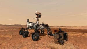
NASA’s team developed a system involving three camera-pairs, each recording one-third of the 15ft conical surface, using a plywood replica. They printed their speckle-pattern on vinyl wrap which could be applied without leaving a residue. DIC systems from Correlated Solutions were again used for these key tests.
“It was a high-profile test, but ultimately uneventful, because the heat-shield performed flawlessly,” Dawicke says. “They were able to fly and now we have high-resolution data of the heat-shield under load to validate FEA models.”
As camera technology evolves, so too will DIC applications. Dawicke sees growing demand for direct FEA comparison – for capturing the effect of flow-fields on structural behavior in wind-tunnels, for filtering out generated light to enable DIC at high-temperatures. Drones could also play a role.
“Positioning cameras around large test-articles involves difficult angles and hardware which can move during a test,” says Vieira. “Flying the camera-bar on a drone, which could lock itself into position and shoot an area with confidence, could be a perfect solution.” Collaborative robots could also support DIC in future. “GOM’s Scanbox system already uses stereo technology for automotive dimensioning,” Vieira adds. “Positioning cameras with a robot arm could bring manufacturing flexibility to test environments.”


