by Gunar Leonhardt, Project Flight Test Service,
This report introduces the preliminary development results of a system for the measurement of Control Surface Deflection Angles on small UAV’s. A solution is presented that dispenses with the use of potentiometers in order to be able to carry out measurements even in very small installation spaces. Initial tests have shown that the presented system can be installed and used in the practical testing of digital flight control systems of UAV’s. But more practical and detailed tests are needed to validate the system.
The development and construction of unmanned aerial vehicles (UAV’s or RPAS) and vehicles for subscale flight testing (SFT) has increased significantly in recent years. Both in the area of vertical takeoff and landing aircrafts as well as in the area of horizontally takeoff and landing aircrafts. Among them are many very small fixed wings UAV’s or demonstrators who are currently under development, construction or testing.
Also, fixed wing UAV’s must be equipped with a flight control system to be operated. Today’s digital flight control systems (DFCS) for UAV’s bear usually very large similarities to the digital flight control systems used in manned aviation. But this also means that this system must be tested in order to make it safe for the operation in an UAV or an SFT vehicle.
The testing of DFCS’s is a major challenge and requires a lot of knowledge and the capturing of many important parameters. One of these important parameters is the control surface deflection angle. The control surface deflection angle should be measured both, on the ground and as well as in flight, in order to make this parameter available to the DFCS, to the telemetry system and to the ground control station during flight tests via telemetry system.
Commonly, variable resistors were used to measure the control surface deflection angles in manned and unmanned aviation. Here, the resistor is mechanically connected to the control surface and movements of the control surface lead to a change in the value of the variable resistor. A connected voltage then changes equal to the variable resistor value and the emitted voltage corresponds to the control surface deflection angle. Unfortunately, the smallest potentiometers are sometimes too large to fit into a small UAV or SFT vehicle. The installation space in a wing or a horizontal stabilizer of a small UAV is often simply too small for a potentiometer.
It is also important to mention that the friction of a variable resistor, can lead to the obstruction of the control surface movement. Whereas this is hardly significant in a manned aircraft, this can be of great importance to a small UAV.
Background
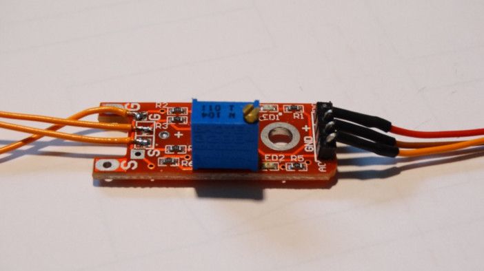
For a long time, the project flight test service was looking for a solution to replace variable resistors. The solution was found in form of a Hall-sensor module. These sensor modules are delivered by a large online retailer, are relatively inexpensive and the necessary electronics are send in one package. Such a module seemed very suitable to use for the measuring of control surface deflection angles in small UAV’s without mechanical connection and load to the control surface. One of such commercial off-the-shelf modules is shown in Figure 1 below.
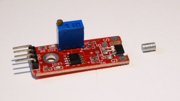
The KY-024 module has the dimensions of 42x15x14mm and the module is operated with a DC voltage of 5 volts. The hall-sensor is located on the far right of the board. It reacts to a magnetic field of a small permanent magnet (Diameter 3 mm) and provides an analog output voltage, like a potentiometer, depending on the angle of the magnet to the sensor. This principal permits the measurement of control surface deflection angles, when the sensor and the magnet are mounted in the required place. To do this, the sensor must first be removed from the board and then be reconnected to the board with thin cables. Please see figure 2 below.
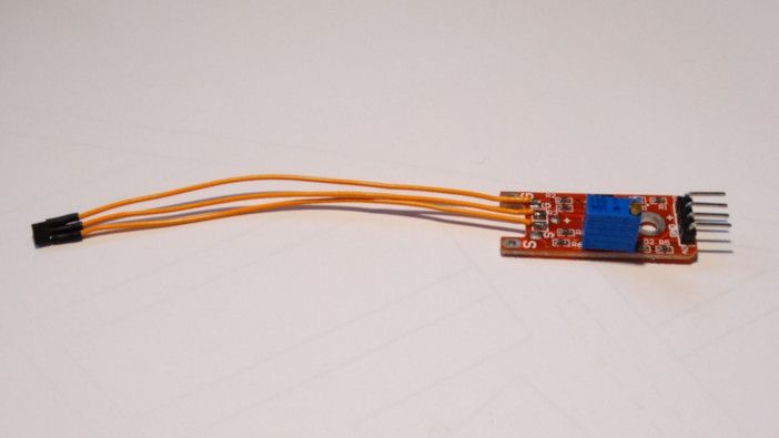
Now the connections for the supply voltage and the analog output voltage, on the right hand- side of the module, must be provided with cables. Please see figure 3 below.
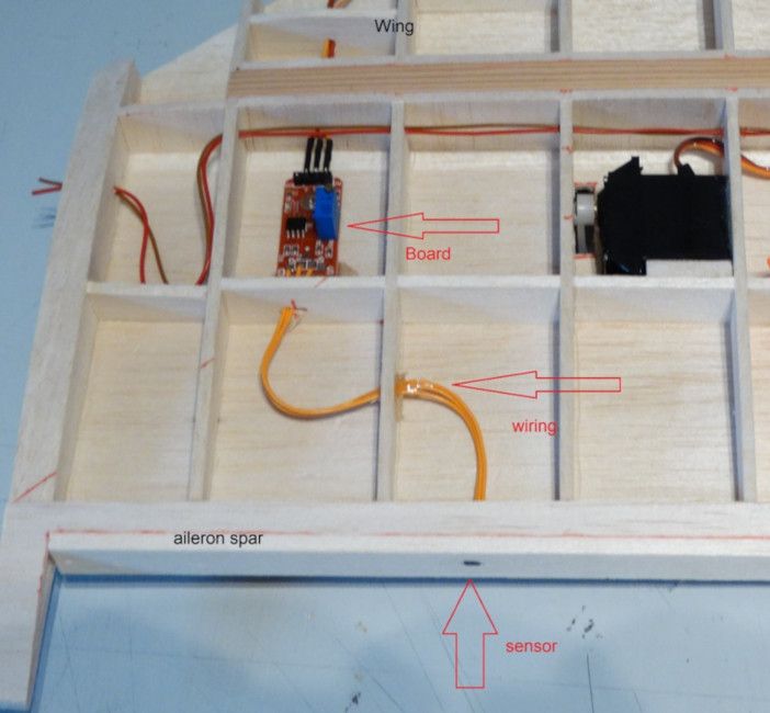
Fig. 3 Complete wiring of a Hall- sensor module (Image: G. Leonhardt)The module prepared in this way is now ready for installation in a wing or a horizontal stabilizer. It is important that the sensor is positioned precisely to enable an accurate measurement. The sensor is installed in the aileron spar of the wing and the board in a wing section. The permanent magnet is positioned in the leading-edge of the aileron so that it is installed exactly opposite the sensor. The installation principle is shown in the next figure. Please see figure 4.

In the case of practical use, the installation of the components in a wing is presented in the next figure. Please see the following image.
For a first test, the module was electrically connected to a telemetry voltage sensor MU-3 by JETI. This sensor can detect and send the analog output voltage of the hall sensor module to a telemetry system. The sensed data can then be visualized by a PC program. An example of the visualization is given in the next figure. Please see the graph in figure 6 below.
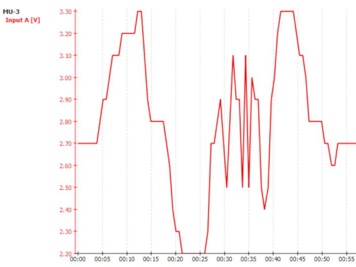
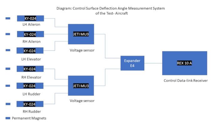
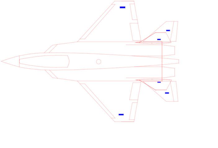
A voltage of 2.7 volts corresponds to the middle position of the aileron, a voltage of 3.3 volts to a full negative deflection angle and a voltage of 2.2 volts corresponds to a full positive deflection angle of the aileron. In the case shown, the aileron was moved not with an actuator but by hand, so the curve may become a little angular. For this first test, however, the results were quite satisfactory, and the author is sure that the system can do its job. A more detailed ground and flight test of the system will take place this autumn. These tests are required to verify the accuracy and reliability of the system. The aircraft selected for these tests is equipped with six KY-024 modules. Please see figures 7 and 8 below.
For more information on this measurement systems and other work, please contact Project: Flight Test Service at flight-test-service@web.de


