Words by Abigail Williams
Several non-destructive testing options and approaches are available to engineers when inspecting parts made from composites in aerospace.
A well-considered approach to selecting the best technique will depend on several factors and include technologies such as high power x-ray and CT (computed tomography) machines.
Also affecting decision making is that the use of lightweight composite materials in aerospace is continuing to grow. Engineers are increasingly faced with the challenge of ensuring composite materials are up to the task they are designed for in aircraft.
However, the use of composite materials in aerospace applications can be complex and many challenges still remain to ensuring reliability and longevity, as evidenced by the manufacturing problems faced by Boeing with the fuselage of its 787 Dreamliner last year.
Furthermore, there are several technological innovations in the field of non-destructive testing (NDT) and composites which influence the way composites are inspected in the coming years.
Existing methods
A test engineer’s choices relating to the most appropriate method and technique for inspecting composite parts in aerospace are driven mainly by the material characteristics and the type, size and orientation of what is being detected or measured – with such choices further constrained by a range of other factors, including surface condition, part geometry, access, environment, cost and time available.
As Ian Cooper, NDE Group technology strategy manager at TWI explains, when inspecting composites, engineers are generally interested in the internal structure of the part and not just the surface: “Volumetric methods such as radiography and ultrasound interact directly with the internal structure and are the most commonly used.
“Other emerging methods such as microwave and terahertz imaging also show promise for the inspection of materials such as glass fiber reinforced plastics [GRP] and aramids but is less useful on carbon. Other methods, such as thermography and shearography can give indications at the surface that are modulated by features within the part, providing the right excitation or stressing methods are used.”
According to Cooper, ultrasound is currently “by far the most common method” used to inspect composite parts – with techniques available that require access to either both sides or one side of the part.
Advanced imaging techniques capable of resolving types of flaws that were not previously readily detectable are now available. In addition, transducers that can be easily coupled to robotic systems and automated defect recognition (ADR) algorithms are also under development around the world.
“Because there are large signal losses at the air to part interface, ultrasound is usually coupled into the part to be inspected using water.
“Historically, use of this method has been limited to applications where immersion or wetting of the part is possible. However the development of modern techniques such as laser ultrasound, impedance matched rubbers and hybrid air-coupled systems means that this is no longer the limitation it once was,” says Cooper.
“The main limitations of the method are scattering and refraction of the sound energy by the fibres within the part – which is particularly challenging for thicker components – and the need to have a sound path to the area of interest,” he adds.
Elsewhere, Jason Hwang, non-destructive inspection R&D engineer at the Royal Netherlands Aerospace Centre (NLR), agrees that the options and approaches available when inspecting composite parts in aerospace generally depend on size, material and the intended use and load on the parts.
“Apart from more traditional and proven methods, such as C-scan, many researchers are looking into novel techniques for various challenges. For example, there are currently vast developments in contactless methods, which can provide a quick overview of fault features, overcoming long inspection times,” says Hwang.
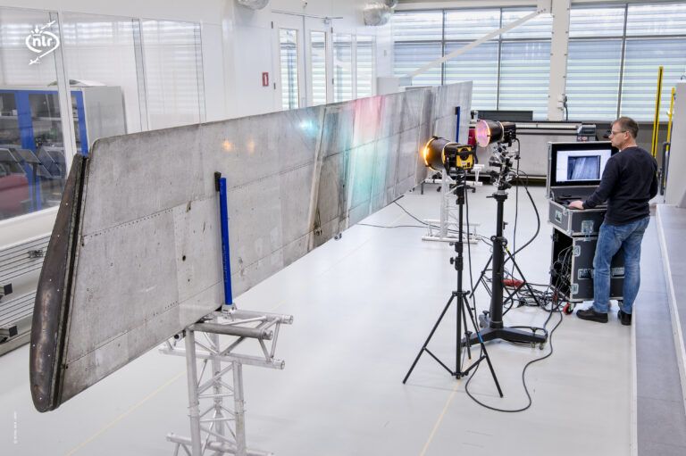
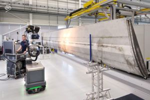
“Thermography and shearography are also good examples of techniques suitable for final product and even in-line manufacturing inspection. NLR is currently looking into these solutions for aircraft manufacturers – and the lower skin of the Multifunctional Fuselage Demonstrator, which is manufactured by NLR, is a realistic case for investigations,” he adds.
Radiography
When it comes to the use of x-ray, gamma ray or CT scanning, Cooper believes that radiographic techniques have been used “very successfully” to detect water ingress and crush damage in aluminum honeycomb cored components and to confirm the placement and integrity of metal inserts in hybrid structures. However, because of the need to orient the beam in the same plane as a crack to be detected, he observes it is “less useful for the detection of delaminations, disbands or cracks that are parallel to the components surfaces”.
CT systems typically work by rotating components through 360˚ whilst capturing multiple Digital Radiography (DR) images at various projection angles. These are combined within the software to produce a 3D image of the component that can be sliced on any plane.
“This means that the technique is less sensitive to flaw orientation, but is limited to components that are small enough to fit within the enclosure. Previously, parts were limited by the size of the detector panel, but new technologies are able to effectively increase the detector size by translating the part or detector panel and repeating the scan and combining the scan data,” says Cooper.
However, although fast acquisition systems have reduced the time taken to acquire data, Cooper argues that the time required to analyze the scan results “adds cost to the process.”
“ADR algorithms are being developed and this will help to reduce the cost of inspection. The main barriers to uptake are the high capital costs of systems, enclosure size, the management of hazardous radiation and the high skill levels required,” he adds.
Accelerating development
According to Brett Muehlhauser, R&D technical fellow at North Star Imaging, CT scanning provides “substantially more comprehensive data than the superimposed product data captured within the individual 2D images”. As a result, this data quality has quickly propelled CT into what he describes as a “go-to technology in the development and inspection of composite structures”.
“DR and CT are now applied in the development of most new composite manufacturing methods and products, the initial product inspection, in service inspection and failure analysis and failure investigations,” says Muehlhauser.
“The application of CT over the years has been responsible for helping to accelerate the development and validations of several new composite fabrication processes. NSI CT systems are now currently being employed in the evaluation of various sizes of flight critical components as well as in the large composite structures used in many military and commercial aircraft that are flying today.”
NDT for Additive Manufacturing
In recent years, NDT techniques have also emerged as increasingly useful tools for in-process monitoring for additive manufacturing. One such application is NDT monitoring using the RAM (Resonance Acoustic Method) – which makes use of a part’s own natural frequencies for inspection purposes.
The technique works by exciting a part and capturing its natural frequencies or resonances. Greg Weaver, president at WeaverNDT says, “This data is then used to monitor the individual component responses compared to a reference or known population of acceptable components.”
In the aerospace sector, Weaver reveals that the main application of NDT-RAM consists of testing each build of additively manufactured parts and inspecting if that build is consistent with the desired resonance outcome. “This can provide early detection of flaws, material consistency, laser issues, and a variety of other issues. This method can even be used to non-destructively correlate tensile coupons to their ultimate tensile strength,” he says.
“For NDT-RAM specifically, one of the main recent developments is the range of possible usable frequencies has been doubled and the resolution has been enhanced,” he adds.
Although more recently developed approaches like CT-scanning are becoming more commonly used for NDT and inspection, Muehlhauser observes that the older technique of ultrasonic scanning, which has been used for the evaluation of composite aircraft structures for over four decades, can still be employed in a complimentary capacity.
“Numerous technology advancements have been made providing for an increase in scanning resolution as well as scanning speeds. In general terms, ultrasonic scanning typically provides lower resolution for many types of discontinuities when compared to micro-CT, however CT is often limited by the size of the product that can be scanned,” he says.
“Overall, the two technologies are found to complement each other more than compete. In some cases, both technologies are employed in the evaluation of products, with the overlapping strengths of each method providing an even more thorough product evaluation,” he adds.
Future trends
Looking ahead, Muehlhauser predicts that rapid advancements in composite materials and manufacturing processes will continue to drive the creation of new inspection technologies and techniques that will provide for the “better resolving ability of new manufacturing anomalies that may impact product performance and integrity”.
“As additive manufacturing expands into the arena of advanced fiber-reinforced composite structures, there are new demands to provide for a better understanding of the correlation between product performance and the detailed internal product structure as captured in CT scanning,” he says.
As the physical size of composite structures grow, Muehlhauser points out that new innovations in DR and CT imaging technologies are also being developed to provide for full imaging of larger structures.
“One of these advances involves the employment of NSI’s MosaiX precision x-ray detector movement to provide for the automated stitching of multiple DR images. This technology provides for complete DR and CT data of the entire structure,” he adds.
Next generation materials for aircraft
The Multifunctional Fuselage Demonstrator, a leading aerospace composites project tasked with developing a next-generation thermoplastic-based fuselage demonstrator is making steady progress.
As Ralf Herrmann, Multifunctional Fuselage Demonstrator (MFFD) project leader at Airbus Operations explains, the key objective of the MFFD project is to validate combinations of airframe structures, cabin, cargo and system elements by applying new design principles and advanced system architecture in combination with the next-generation cabin, using thermoplastic composite to enable production rates “of at least 60 large passenger aircraft per month, while significantly reducing fuselage weight and recurring costs”.
“The weight reduction would in turn bring fuel-burn reductions – and therefore a reduction in the CO2 and NOx footprint – by substantially reducing the overall aircraft energy consumption due to lower weight and improved architecture and integration,” says Herrmann.
According to Herrmann, the project team is currently focused on making the demonstrator manufacturing tooling, as well as on material procurement and testing. “The Critical Design Review in autumn 2019 gave us the starting signal for the realization of the demonstrator parts, firstly as manufacturing trials for process evaluation, quality assessment and data for tolerance management.”
Drawing on the results of this phase, partner organizations will then work on design updates aimed at process optimization and quality improvements. A digital model with a complete representation of material properties and demonstrator features will also form part of the further refinement of the ongoing Digital Mock-Up (DMU) process.
“Material data are coming from the testing of coupons and small test articles, with a major focus on thermoplastic welding and the respective equipment, as well as on forming. In 2021, large scale manufacturing trials are foreseen, with the goal of delivering the major components – including the upper and lower half-shell – to final assembly over the course of the second half of 2022,” he adds.
In addition to technological innovation, future approaches adopted by engineers for the NDT of aircraft composites are also likely to be influenced by the ongoing development of industry standards. Historically speaking, Cooper explains that aerospace industry standards have tended to be “developed by the primes to reflect their own materials and manufacturing processes, as well as the specific performance requirements of the parts to be inspected”.
“The main difficulty has always been the huge variation in materials and manufacturing processes, coupled with the need to find a sufficiently generic structure to make it worthwhile producing a public standard,” says Cooper. “But standards are emerging and there are a number of aerospace specific ASTM standards available covering thermography, shearography, ultrasonic, radiography and acoustic emission,” he says.
Hwang believes the sector is undergoing “great developments” in virtual testing, automation of inspection and feature recognition. “These developments look promising because they enable costs to be reduced significantly. However, in order to implement these techniques, the technologies not only has to mature, but standards and regulations have to adapt.”
Related content
Introduction to non-destructive testing
Watch now: Next Generation NDT – working with composites
Opinion: A sustainable future for NDT
Roundtable on NDT imaging for inspection and analysis of aerospace parts and products


