A new vertical axis test rig for the compressors, turbines and fans that will play a key role in the next-generation of aero-engines is set to boost propulsion research at the University of Cambridge’s Whittle Laboratory.
Developed by UK-based Frewer Engineering in partnership with manufacturers the Hyde Group, the vertical test rig’s closed-loop system and vertical design pushes the boundaries of testing capabilities and will accelerate the development of more efficient and sustainable aircraft engines.
The test rig is a key part of the University of Cambridge’s £58 million (US$76 million) New Whittle Laboratory, home to the UK’s National Centre for Propulsion and Power (NCPP).
The Whittle Laboratory originally opened at the University of Cambridge in 1973 to help develop technologies to enable mass air travel. The New Whittle Laboratory’s mission, which is set to open in 2026, is again concerned with aviation technologies. However, this time the aim is to make aviation more sustainable.
The turbomachinery test rig represents a significant leap forward for the Laboratory. The rig will be used to test compressors, turbines and fans for aerospace propulsion systems, at different temperatures and air densities up to transonic speeds. Frewer Engineering were able to draw upon their decades of experience working with specialised gas turbine test rigs to successfully design the multi-purpose platform.
Vertical for speed and flexibility
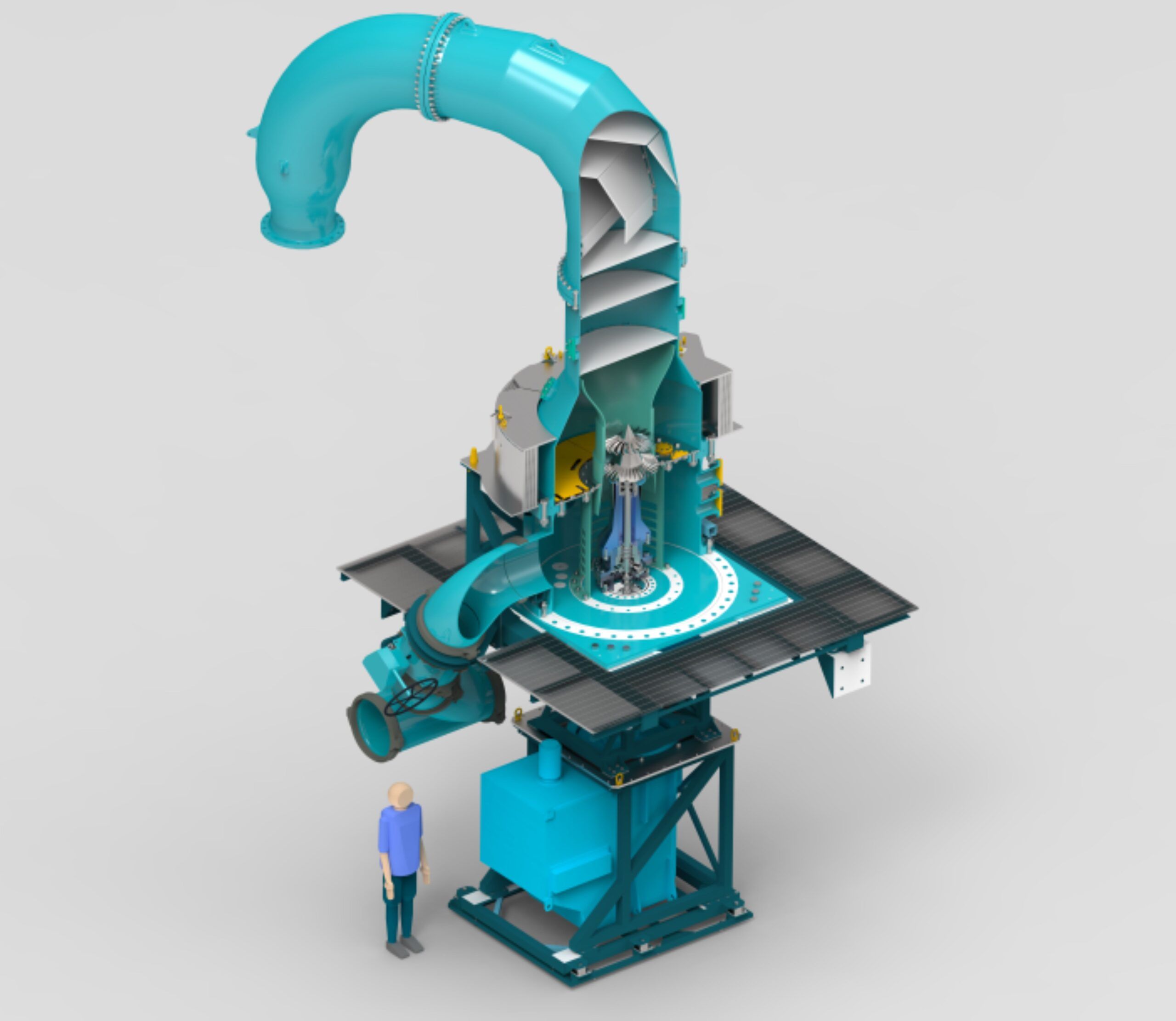
Compressor and turbine test rigs are most often horizontal, but Frewer Engineering has designed the New Whittle Laboratory’s rig to be vertical. This approach simplifies the changeover process for tests and required careful engineering and integration into the Laboratory’s building.
Simon Apsley, chief engineer at Frewer Engineering said, “We’re hoping to be able to take an experiment out and switch it over in around 30 minutes.
“The U-shaped arrangement at the top and surrounding containment safety ring can easily be lifted off the rig by undoing only two flanges. Once lifted, you have full access to the test experiment at a comfortable working height.”
A 30 minute changeover would be a significant improvement over horizontal and other predecessor test rigs, where changing experiments can be time-consuming and complex due to difficulties in lifting and aligning the test articles. To optimise the process, Frewer Engineering’s team used virtual reality simulations to recreate crane operations and ensure a good line of sight for operators during changeovers.
Closed-loop for efficiency and power
The rig operates as a closed-loop air system, another feature that sets it apart from many traditional open-ended rigs. This design offers several advantages said Apsley: “The air is compressed in the loop, up to higher pressures and densities, then pumped around the circuit. This means engineers can simulate a larger range of flight conditions using the greater range of air pressures, densities and viscosities.
Tests can also be run at low air-pressure and partial vacuum, further expanding the test envelope. This caused some complications for the oil lubrication systems, moving oil the right direction in a partial vacuum – one of the many challenges our engineers overcame in developing the rig design.”
The closed-loop design not only expands the testing envelope but also improves efficiency. “The rig is cheaper to run because, once running, you don’t have to use as much energy to bring in and continuously condition fresh air from the atmosphere, as you would for an open-loop system” said Apsley.
The system will achieve blade-tip air speeds of up to Mach 1.3, enabling researchers to test components under extreme conditions that closely mimic real-world, high-altitude operating environments, within the test cell.

Around the bend
The company’s expertise in fluid mechanics was particularly crucial in addressing one of the rig’s key challenges. “The air comes into the rig around a large horseshoe bend and needs to be conditioned and presented into the test cell as a uniform clean airflow,” Apsley said. “It’s hard to achieve this around a bend – secondary flows around the corner invite recirculation, separation and unsteady flow features which will disrupt the experiment if left untreated.”
To solve the problem, Frewer Engineering used a combination of expansion techniques, louvers, flow control screens, and shaped liners in the test cell, which were optimised using CFD analysis. The solution ensures that the air entering the test section is free from significant disturbances, which is critical for accurate experimental results.
Vertical axis test rigs aren’t new, but this one combines size, speed and flexibility in a way that hasn’t been achieved before said Apsley.
“This rig brings all previous testing work and experience into one place, with higher speeds and higher pressures available,” he said. “Researchers would have to repeat an experiment several times on several different rigs to achieve the same data set.”
The rig has a health monitoring system that uses a range of sensors to ensure it is performing correctly. Beyond this it offers additional allocated room for researchers to add their own instrumentation.
The rig is highly configurable and can accommodate a range of experimental setups and measurement needs. “We’ve provided a significant amount of spare capacity for routing different items of instrumentation in and out,” Apsley said.
Frewer Engineering is an agile company, staffed by engineers with expertise in areas such as fluid dynamics, aerostructures and rotor-dynamics. Their streamlined processes and close-knit team enables an interdisciplinary approach to problem-solving and aims to rapidly iterate between design and structural and CFD analyses, faster than their competition.
Propulsion advances
The rig is scheduled to be commissioned next year, ahead of the new Whittle Laboratory’s opening.
The primary goal of the test rig is to accelerate the pace of innovation in aerospace propulsion. It currently takes up to 10 years to develop a new engine technology so it’s mature enough for deployment. The goal of the Whittle Laboratory is to significantly reduce the time it takes to develop technologies for more sustainable aviation. The rig will therefore support research into new engine technologies including geared turbofans, hydrogen fuels, and Sustainable Aviation Fuel (SAF) propulsion systems, as well as electric fans.
“If anyone’s got a chance of reaching our net zero target between now and 2050, we need to invest in, and accelerate, the pace of development and testing for these types of new engine technologies,” Apsley said.
By enabling faster testing and iteration, the test rig at the New Whittle Laboratory could significantly reduce the time it takes to bring new propulsion technologies from concept to market. This acceleration is crucial for meeting increasingly stringent environmental targets and maintaining competitiveness in the global aerospace industry.


