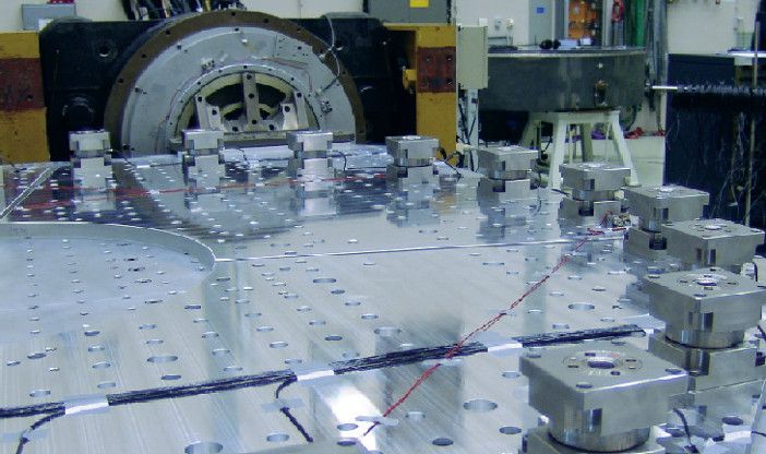
Satellites undergo a stressful journey from the launch pad until they reach their final orbit. A failure in any one of their components may result in malfunctioning of the satellite, which is expensive and will delay the program for years. And no “repair service” is available in case the satellite is damaged!
This makes it vital for all space systems – such as satellites – to undergo an intensive program of pre-launch tests.
These include the force limited vibration test (FLVT). This test, conducted at ground level, involves subjecting the satellite to all vibrations that are likely to occur during its flight from earth to orbit. If a problem arises, corrective actions can be taken.
Vibrations are generated during these flight phases:
- launch phase, due to acceleration and operating engines
- transonic flight, when the sound barrier is broken
- near orbit, when the protection cover is removed from the launch vehicle
Each of these phases creates specific spectra of different vibrations.
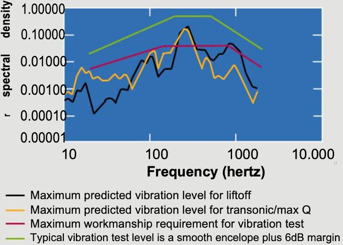
The above shows a typical spectrum of vibrations created at lift-off and during transonic flight. The light green curve depicts the test level. It is slightly above the expected levels, but should not lead to overtesting.
The FLVT aims to be a realistic test that simulates real conditions.
Typically, vibration tests are carried out on shakers.
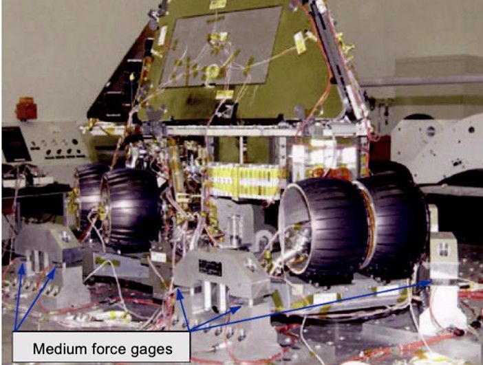
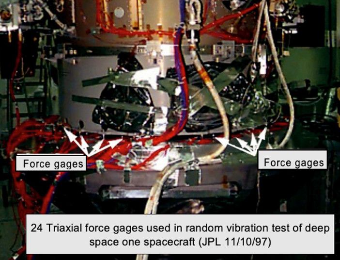
However, there is one problem: the shaker and the launch vehi-cle each display different dynamical behaviors – the mechanical impedance of the shaker is very high at its resonance. This may lead to overtesting at the shaker’s resonance frequency. The dynamic forces acting on the test object can be far too high, so the force must be limited. This is achieved by positioning force sensors between the test object and the shaker:
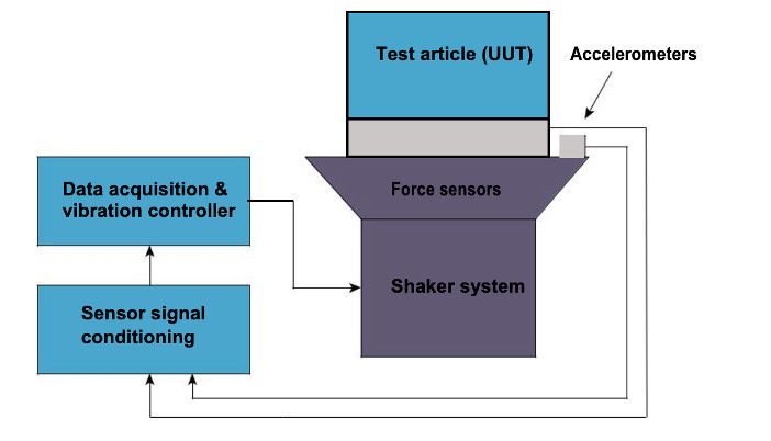
The force sensors will limit the maximum vibration at the shaker’s resonance, which is the main objective of an FLVT. The FLVT was introduced by Terry Sharton at the Jet Propulsion Laboratory (JPL) in 1990.
FLVT measurement with piezoelectric sensors
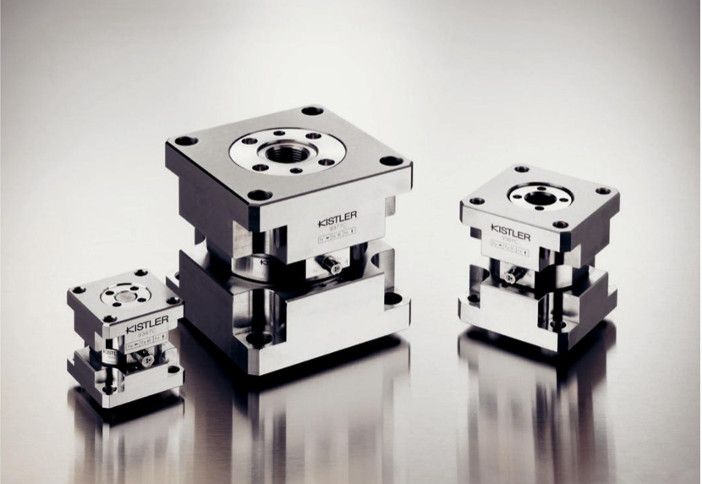
Force sensors for FLVT must be rigid, and they require a wide measuring range. Therefore, the NASA HDBK 7004C states:
“…The high degree of linearity, dynamic range, rigidity, and stability of quartz make it an excellent transducer material for both accelerometers and force gages.”
Type 9347C, 9367C and 9377C are very common examples of force links.
Typical FLVT configuration
The ring configuration is a very common layout. Multiple force links are mounted between a ring-shaped top plate and bottom plate. This configuration provides a flexible layout for a large variety of test objects.
Examples
This article was supplied by test and measurement company Kistler.


