Blade runner
A new flight test project led by Airbus spearheads an EU effort to see if laminar-flow wings can be produced on an industrial scale
Airbus is busy performing the first element of a 150-hour flight test program with an A340-300 modified with natural laminar-flow (NLF) outer-wing sections that could lead to a significant reduction in drag and consequent fuel consumption. After a September 26 first flight, the manufacturer planned to fly the A340BLADE (Breakthrough Laminar Aircraft Demonstrator in Europe) test aircraft two or three times a week in October and slightly less often in November.
Ahead of the 3 hour 38 minute first flight, from Tarbes in southern France (where the aircraft had been modified) to the Airbus Flight and Integration Test Centre in Toulouse, a 10-strong team of pilots and test and flight test engineers spent several months training in a simulator to familiarize themselves with planned flight test instrumentation (FTI). A much larger working party of 70 performed the 16-month FTI cabin installation in Tarbes, while Airbus teams from Bremen, Germany, and Broughton, UK, worked to fit the A340BLADE demonstrator’s outer wings. Another German team installed an infrared camera pod on the fin.
The A340BLADE is “the first test aircraft to combine a transonic laminar-wing profile with a true internal primary structure”, says Airbus. Laminar – or streamline – flow relates to the boundary layer of air that follows the shape of the aerofoil until disrupted by surface contaminants and other factors that generate turbulence, reducing lift and increasing drag.
During the first test flight, engineers were able to observe areas of laminar flow on both new wings during what was mainly a shakedown flight for aircraft and instrumentation. The flight saw the A340BLADE achieve a speed of Mach 0.78 and cruise and maximum altitudes of 32,000ft. “We achieved our objective to fly at the design Mach number, at a reasonable altitude, and check everything was fine,” reports flight test engineer Philippe Seve. “We checked that the FTI was working as expected, to identify further fine-tuning for the next flights.”
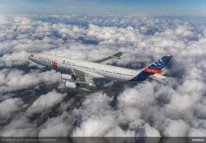
The A340BLADE during its maiden flight, from Tarbes, France to the Airbus Flight and Integration Test Centre in Toulouse
By mid-October, the machine – which is the company’s original A340-300 prototype (MSN001) – had made two more flights to confirm the low- and high-speed flight envelope, including stalls and flutter.
Initial flying scheduled for completion this year includes assessing aircraft-handling qualities, extending the flight envelope, and taking first measurements of laminar-wing performance, according to Airbus Research and Technology senior vice president Axel Flaig. A second round of flights in 2018 is planned to “extensively test and characterize laminarity robustness in representative operational conditions”.
The campaign is primarily intended “to validate the area of laminarity that can be achieved for a large variety of cruise-flight conditions with respect to altitude, Mach number and wing loading”, according to the Clean Sky joint undertaking, an EU research program that aims to reduce aircraft CO2, gas and noise emissions.
Fateful eight
Clean Sky’s swept-wing future aircraft (SWFA) integrated technology demonstrator program, of which BLADE is a part, addresses integration of related new technologies for large aircraft. The JU says that demonstrating an NLF ‘smart’ wing with associated advanced FTI equipment represents the first of eight technology streams in the SFWA flight-demonstration work package.
“For a typical short- to medium-range aircraft, the calculated drag benefit is up to 8% at typical Mach 0.75 cruise flight, which translates to around 4.5% fuel-burn reduction for a typical mission,” says Clean Sky.
Airbus hopes to confirm a 50% lowering in wing-friction drag, which will translate into “up to 5% block-fuel and CO2 emission reduction” if the technology is applied to short-range aircraft flying up to 800 nautical miles.
The new NLF wing sections are close in size and configuration to a possible future wing for a short-range, single-aisle airliner, says Airbus. Initial thoughts had envisaged a complete wing for testing on a smaller aircraft, but BLADE project leader Daniel Kierbel explains that using a smaller proportion of a larger wing reduces the potential for loss of control while exploring the limit of laminar flow.
Rapid recent development of numerical flow-simulation tools has enabled the aerospace industry to design, build, demonstrate and validate an optimized NLF wing, according to Airbus, which has defined (and validated through ground testing) “aerodynamic flight-control laws related to the specific shape of the natural laminar wing”.
The BLADE project intends to test the robustness and sustainability of natural laminarity in operational service so that – by specifying production-tolerance requirements – manufacturers can properly specify and design laminar components (including wings) for future commercial aircraft.
The program’s primary aim is to accelerate future industrialization (or mass production) of laminar wings, for which previous technology has been insufficiently mature for commercial aviation application and has not been fully validated in flight. “The past 50 years have seen more than 70% improvement in relative fuel-burn per seat and 90% in noise emissions, but a practical application of laminar flow has not been achieved,” says Flaig.
Pointing out that natural (or passive) laminarity can be achieved through aerofoil shape while hybrid (active or passive) laminar flow can be generated with, say, boundary layer suction, Kierbel outlines the many factors that influence the presence of NLF on an industrial wing.
First come external considerations outside the wing. These include leading-edge and wing contamination (such as de-icing fluids, dents, dust, erosion, grease, insects and scratches); atmospheric disturbances; and acoustic disturbances and vibrations.
Secondary (or internal) factors can comprise such considerations as system integration, deformation of fastener heads and joints, gap-filler material, and local and global wing deformation.
Split decision
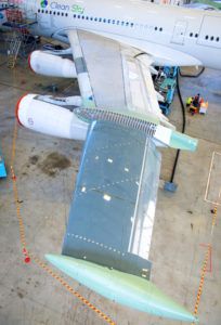 The A340BLADE combines a transonic laminar wing profile with a true internal primary structure
A340-300 MSN001 is being used because it is available and has a natural wing split that permitted replacement of the outer sections. The biggest external change following modification is the introduction of the two representative transonic laminar outer-wing sections.
Clean Sky says that experiments to better understand and control the laminar-to-turbulent flow transition, which is influenced by (for example) isolated surface gaps, steps and holes, prepared the groundwork for full-scale wing design and flight testing – “the first time such realistic test data has been available for future aircraft design”.
The 8m-span (26ft) NLF sections were designed and manufactured with partners Saab of Sweden and GKN UK for two different solutions, each complying with stringent accuracy, stability and tolerance requirements to maintain laminarity in all flight regimes.
Kierbel says that NLF wing architectures involve two options – one with a one-piece carbon fiber-reinforced plastic (CFRP) wingskin and leading edge (supported by integrated wing-rib feet and spar cap) on Saab’s port outer wing, and the other with a mechanically fastened CFRP wingskin and metallic leading edge, interrupted by a joint at the forward spar, on GKN’s starboard outer wing.
Airbus had to design a wingbox to interface the existing wing with the NLF sections, which are very evident because they feature a 20° sweepback (about 10° less than that of the original unit). Inside the aircraft, a specialist FTI station has been installed.
Kierbel says that replacement of the outer wings and modification of the A340 tailfin to accommodate a camera pod (to confirm wing behavior) involved “a combination of experience and a technology bridge”. Overall, the Tarbes engineering work involved “21 European partners, 500 contributors and 6,500 parts”.
Major steps in developing the A340BLADE demonstrator included the manufacture of several special components, according to Clean Sky: large aero-fairings to separate the new outboard NLF wing sections from the original turbulent inboard wing; wingtip pods to ensure a defined flow pattern at the outboard end of each NLF section and to contain flight test equipment (with optical access close to the laminar wing), with a diffusion zone passing wing loads and torque from the NLF section to the datum wing structure; and a digital mock-up of the NLF wing outboard of the datum wing’s number-one (port outer) engine.
Wind-tunnel tests (see Tunnel vision, p25) were conducted to check low-speed performance and to test a Krueger leading-edge anti-contamination device used to influence airflow over about 20% of the new NLF section span. Flight testing is “intended to demonstrate the device’s potential to shield the upper wing surface from contamination”, according to Kierbel.
He points out that laminar flow is “much better at lower speed, but requires transonic airflow”. As well as containing infrared cameras, the tailfin pod provides mounting for an altitude/airspeed-calibration trailing cone and two cone-flow cameras.
FTI was a challenging and innovative aspect of the BLADE project, according to Airbus. In addition to standard inflight measurements of acceleration, pressure and temperature, the program partners needed to measure: laminar-flow transition location on the wing (using surface-mounted heat-sensitive film and infrared cameras); NLF wing-surface quality and deformation (reflectometry); NLF wing-shape in flight (with loads and inertial sensing); and NLF wing deformation (via an internal mechanical sensor).
To this end (and using such testing on an aircraft for the first time), Airbus says there are “hundreds of points to measure the waviness of the wing surface” to help ascertain its influence on airflow laminarity. “Airbus will simulate every type of surface imperfection in a controlled manner, so that the tolerances for building a laminar wing will be fully known.”
The manufacturer says the project also represents the first use of pod-mounted infrared cameras to measure wing temperature and of an acoustic generator to measure the influence of acoustics on laminarity. The wingtip reflectometry system that gauges overall inflight deformation in real time is also said to be innovative. As viewed through transparent apertures, the latter record reflections on the upper wingskin of a diagonal-striped pattern on the wingpod where the NLF outer wing is attached, concludes Kierbel.
Tunnel vision
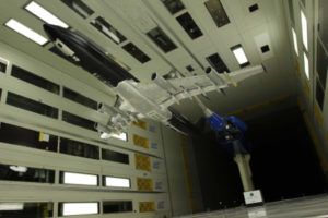
A critical step in the flight-clearance process for the BLADE demonstrator aircraft – Airbus A340-300 MSN001 – was wind-tunnel measurements in the German-Dutch Wind-Tunnels large low-speed facility (DNW-LLF) in Marknesse, the Netherlands, in early 2014. Low-speed aerodynamic tests were carried out on a 1:10.6-scale model in the tunnel’s closed 8 x 6m (26 x 20ft) test section to represent the flying demonstrator under atmospheric conditions.
Having gathered data for the standard A340, a main objective was to check the effect of an installed natural laminar-flow (NLF) outer-wing panel. Other goals included: studying ground effect, downwash and handling qualities (effect on longitudinal and lateral control and stability from the use of ailerons, flaps, spoilers and rudder); examining wing airflow and stall behavior to obtain information on boundary-layer transition (using infrared thermography); and using optical techniques to measure deformation to establish local attitude changes due to wing torsion.
Anticipating the technology now being employed on the real aircraft, the testing used infrared thermography to locate the boundary-layer transition point on the NLF panel. The exercise also yielded valuable knowledge on the use of techniques such as stereo-pattern recognition for deformation measurements in such wind-tunnel applications.
Blade runner
Airbus leads the BLADE program and with Saab co-leads the SFWA-ITD, which is funded by the EU Horizon 2020 program. SFWA-ITD addresses integration of passive and active flow, and load-control technologies for large aircraft and business jets, aiming to demonstrate that innovative capabilities, concepts and technologies can contribute to a step-change in reduced fuel consumption and noise.
Ultimately the SWFA project will use on-ground or inflight demonstration vehicles aimed at reducing aircraft drag by 10% by lowering wing drag using laminarity, cutting aircraft fuel burn by 20% by integrating advanced engines, and reducing aircraft noise by up to 10dB by engine noise shielding configurations.
Airbus led the structural and fuel, hydraulic and electrical system modifications, which involved 21 design, manufacturing, research and testing partners. It emphasizes that the A340-300 BLADE exercise – “the largest flight test demonstrator ever launched in Europe” – has “no link to any possible future aircraft program”, although “maturity of this technology could possibly be considered for a future aircraft program.”
Flight lab log
The A340-300 BLADE demonstrator campaign, which originated in 2008, is part of a broader program using several aircraft to test new technologies in Airbus Research & Technology’s Flight Lab department. A dedicated hangar was erected at Tarbes in southern France to house the A340-300 (and other Flight Lab projects) during its conversion.
Started in 2008, the following steps have been successfully accomplished by the BLADE team.
2010: Wind-tunnel testing, concept freeze, and natural laminar-flow wings maturity review
2013-2014: NLF Wings maturity-closure reviews
2015: Start of NLF upper cover (wingskin) manufacture and assembly
2016: Start of BLADE working party in Tarbes (jigs and platforms installation), removal of A340-300 original outer wings, assembled
NLF wings delivered to Airbus for painting, and completion of NLF wing-panel join up to original wing
2017: Aircraft “power on”, completion of systems and flight test instruments installation, testing and calibration, and first flight.


